![]()
On this page I thought Id share some various nifty circuits. Some of them are pretty common and standardised and Im not aiming to put any specific restrictions on their use. If you do use them, itd be good if you mentioned my site or whatever, but you dont have to.
Firstly, Im not an expert in circuit design by any means. Far from it, Id say. It might be something I started with probably in the late 1980s, but really I just have a dabble now and then with stuff that might interest me to make, and usually the final result is what Im after. It hasnt been a primary interest in my life.
If youve never done anything with electronic components before, then this page isnt the best place to start. You should know about soldering, perhaps using bread boards, and PCBs. (Printed circuit boards). You dont HAVE to get a PCB designed to suit. You could just use a prototype board in most cases. Also, reading a circuit diagram is also something you should be able to understand. Ive tried to use standardised symbols as much as possible to avoid confusion.
Audio Level Indicator
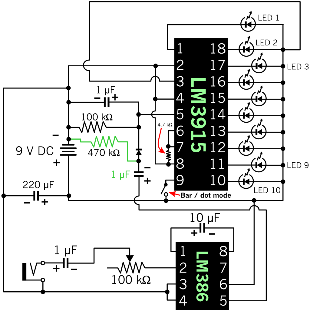 |
This is only illustrated for one audio channel. If you want it for stereo, you need to make a duplicate of all the parts, although you could probably share the large filter capacitor on the power supply. |
Years ago I got Dick Smiths Fun Way 2 audio level kit. It was based on discrete components, and didnt use any integrated circuits. It was also made to be connected in parallel with the speakers on your amplifier. Well, after reading about the LM3914 I.C. back in 2020 or so, I thought I would try making my own level display on that, since it seemed to cut out a lot of excess components. That kind of got delayed until this year in 2022, since I partially lost interest, and had more important things to spend my money on. I also wanted something much more sensitive, which would respond to the lower volume levels of my PCs sound card, especially with my noise cancelling headphones, which require very little amplification, since they do their own amplifying anyway. So this circuit above is designed for such use.
The LM3915 is logarithmic, instead of linear, like the LM3914, (which is more for showing voltage levels of batteries,) and aimed for audio related readings anyhow. You can use the LM3914 or LM3916 in the same circuit, but they behave slightly differently. These I.C.s are actually classed as obsolete, as the original manufacturer pulled the plug on them, as it were. But you can still easily get them, and other companies make compatible versions too. The LM386 shown in the circuit, is a low power, 1 watt amplifier. Im using it to boost the input volume so that the LM3915 responds at lower levels.
I like to know the reason for components in circuits, so Ill try to explain what I can. The 1 µF capacitor whose positive side connects to pin 5 of the LM3915 I.C. is present to hold a charge to keep the L.E.D.s lit long enough for you to see them. This is important for the dot mode especially. The 100 kΩ resistor in parallel with it, I think is to bring down its charge a bit quicker. That I wasnt too sure about, but it was shown in several other circuit designs such as this. The input socket at the bottom left can be connected in parallel with another to provide you with a way to connect your headphones. But remember, this circuit is only for mono use. Youll need to build another copy of it for stereo. But they can share the same power source and 220 µF filter capacitor. If you run it from a battery, this capacitor may not be quite so necessary.
L.E.D. 1, which represents the lowest sound level, connects to pin 1 of the LM3915, and then L.E.D. 2 connects to pin 18, and they work backwards, down to pin 10, which is the loudest level.
The resistor which connects from negative to pins 6 & 7 is usually shown in other peoples circuits as around 1.2 kΩ, but as I wanted my super bright L.E.D.s to be dimmer, I cranked it up to 4.7 kΩ. This is the resistor which sets the LM3915s current limitation to the L.E.D.s. You can reduce its heat level further, by connecting a low value resistor in series with the common side of the L.E.D.s and the positive connection of the power source. I didnt show them in this circuit, but Im going to add extra resistors per L.E.D., since Im using super bright ones in varying colours. Some need more resistance than others to equalise the brightness. As an added bonus, this will also allow the components to last longer. The LM3914, LM3915, & LM3916 I.C.s can only dissipate a certain amount of power before they start running too hot. I think its something like 660 mW.
The 10 µF capacitor which connects from pin 1 to pin 8 of the LM386, is to set its gain to 200. Without it, the gain is 20. The output from pin 5 of this I.C. runs through to a 10 µF capacitor, which I think works kind of like a separator, the same as the one at the input socket. Its recommended that the diode in the centre, is a signal type, like the 1N4148. I didnt have any of these, but I found that the base to emitter of a NPN transistor worked just as well.
Pin 9 of the LM3915 is connected to the positive side of the power supply to make the I.C. run in bar mode, which means all the L.E.D.s from 1 up to the highest current sound level will be lit. If you disconnect it, in my case with a switch, it will run in dot mode, which means only 1 L.E.D. will be on at the top end of the sound level.
You can run the LM3915 with an audio source directly into pin 5, but the result from the L.E.D.s is nowhere near as good. You really need the diode and capacitor on pin 5. The diodes purpose is pretty much to allow the capacitor to charge, because without it, it wont work. I discovered this myself, when trying different component configurations.
Ive made some updates to this, since it didnt work properly. Shame on me! Anyway, the changes are in deep green. The extra resistor prevents the level of L.E.D.s from fading away to nothing. I had issues with my old capacitors which didnt show this as much as when I replaced them with new ones, making me wrongly assume the circuit was correct. I also reduced the 10 µF capacitor between the amplifier I.C. & diode with a 1 µF one, which is more responsive to the treble parts of your music.
Ive finally got this completely assembled, and I should probably mention that a 500 kΩ variable resistor might be more appropriate for louder volume inputs.
L.E.D. Flasher
Next up, Im going to look at a way to flash some L.E.D.s. This is known as a flip-flop / multivibrator circuit, and it goes back to around 1919. (Back then they used valves instead of transistors of course.) Its been done in many electronics books, and its rather easy to find examples of on the Internet too. You could use it for crossing lights on a model railway, for a warning that a door may be opening, model police cars or many other fun purposes.
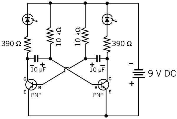 |
Just 2 transistors, 2 L.E.D.s, 4 resistors & 2 capacitors. |
The circuit basically unbalances itself due to component tolerances. When its turned on, the capacitors will charge up, but even though theyre the same value, one will charge up first, and cause the transistor opposite it in the circuit to turn on, which cuts off the other capacitor from charging. Theres a bit more to it than that, but basically it starts a cycle, and the L.E.D.s will flash from one to the other. Its important that the components are closely matched, or the flashing will be uneven. Using different L.E.D.s may even make it seem like one doesnt fully turn off at all. By decreasing the voltage of the power supply, the flash rate will increase. This will also happen if you decrease the value of the capacitors. In fact, if their value is small enough, the circuit could be modified to use a low power speaker instead of the L.E.D.s, which would then make a tone. Something like 0.05 or 0.1 µF in value. In this situation they dont need to be polarised capacitors either. Changing the value of the 10 kΩ resistors, or just one of them, will also alter the speed. In testing, 100 kΩ resistors might be more appropriate. Some circuits show this with a variable resistor too.
The circuit shown is for PNP transistors, but if you want to use NPN, simply flip the polarity of the power supply, L.E.D.s and capacitors.
If you want to add more L.E.D.s in parallel, keep in mind how much current your choice of transistors can handle. (A BC558 type can handle 100 mA & dissipate 300 mW.) If you increase the voltage, you will need to change the 390 Ω resistors too. (On 12 V, with L.E.D.s rated for 2 V at 20 mA, you could use a 510 Ω resistor, since thats the closest value.)
Choosing Resistors For L.E.D.s
Light emitting diodes only require a very small amount of power, and using too much will cause them to overheat, melt and generally stink with a nasty pong. The basical mathematical formula to choosing a resistor which will connect in series with a L.E.D. is: (Power Source Voltage - L.E.D. Voltage Rating) ÷ L.E.D. Current Rating × 1000. So using that for a 5 V power supply and a 2 V L.E.D. rated at 20 mA, you would work it out like so: (5 - 2) ÷ 20 × 1000, and the answer would be 150 Ω. Use a higher value resistor if the value you want doesnt exist. Remember that this is for the maximum specifications of a L.E.D., and if you run them underpowered, theyll last longer.
A Regulated DC Power Supply
This circuit is designed to connect to your buildings high voltage power supply, so if youre not confident in making something for that, dont do it. Remember that coming in contact with your houses 240 V power supply is most often lethal, so everything on that side of the circuit needs to be properly insulated. If you kill yourself, or somebody else, then youre responsible! Dont take shortcuts, and treat this seriously.
If you have some old transformers lying around, you can easily turn them into a DC power source for various electronic projects. Otherwise, if you dont want to build something yourself, youd be better off buying a little regulated switch mode power supply in a plug pack.
This is a basic setup using a 12 V transformer and producing a fixed, 9 V output. |
In the example, is a 12 V transformer. To the right of it, the 4 diodes make up a bridge rectifier. Diodes have a voltage drop of 0.6 V, and taking into account power fluctuations, a little more oomph is recommended for a 9 V output. You can make your own bridge rectifier using 4 power diodes, or you can buy a single rectifier, which basically has 4 diodes inside it. Some of them are cylindrical in shape, square or even rectangular. They will have a wavy symbol on the pins which connect to the AC input, and a + & - for the DC output. Be sure to check what level of current the rectifier can provide. Some may be 1 A or even 3 A, or a lot more.
The capacitor to the right is for filtering. (Its an electrolytic type.) Even though were directing the positive and negative parts of the AC input with the rectifier, you still get a ripple. On the right of that is a 7809 voltage regulator, which is designed to go on the positive side. These should have a heat-sink, and theyre usually only rated for 1 A. Apparently you should not bolt these to an earthed case, nor should the negative part out from the rectifier be earthed. You should also keep the filter capacitor as close as possible, or use a second low value ceramic capacitor right next to the voltage regulator, such as around 0.1 to 0.2 µF or so. The 2nd capacitor is recommended to be a ceramic type, and its not polarised. This just does any final filtering of disturbances in the power.
There are other voltage regulators too, such as the 7805, which does 5 V, and 7812, which does 12 V. Your input voltage should always be slightly higher than the intended output voltage, but each regulator has a maximum rating too, which you should look up.
Be sure to check your transformers power rating and output voltage as well, if you dont know it. You can check the voltage with a multi-meter. (Start from the highest setting and work down.) If youve been salvaging transformers from old appliances, and think one may produce an even higher voltage on the secondary side, it wont be suitable for low voltage circuits. Be very careful if youre looking into microwave oven transformers. This is an area I dont know a lot about, and I think some of them generate very high voltages.
L.E.D. Chaser
Who doesnt love a good chaser circuit?! Im using the traditional 555 timer & 4017 decade counter, but with a Toshiba ULN2803APG darlington transistor array, so you can run up to 500 mA per channel, and not cook the fig out of that poor counter! (Assuming your power supply can handle such a load.) The 4017 I.C.s really arent rated for running high loads of multiple L.E.D.s. You can get away with 2 mA ones perhaps, but not 4 L.E.D.s running in parallel, with each rated at 20 mA. The ULN2803APG, & similar types, also have diode protection built in, so you can also have them run motors, relays and solenoids. You can slap another one in if you want all 10 outputs from the 4017 I.C. Or just use 2 transistors. The output pins, in order, from the 4017 I.C. are: 3, 2, 4, 7, 10, 1, 5, 6, 9 & 11.
There are many circuits which do various effects with multiple L.E.D.s, but this type of circuit will only show 1 L.E.D. lit at any one time. Unless you connect 2 L.E.D.s together, but there is only 1 active output at once. My circuit limits the L.E.D.s to 8, because thats all the ULN2803APG I.C. can do. Other similar darlington transistor arrays, such as the ULN2003N, only have 7 outputs. Because Im not using the whole count of 10, pin 9 of the 4017 I.C., (which is also the 9th output,) is connected to pin 15, which resets the counter. If you dont do this, thered be a gap of 2 counts between the last L.E.D. coming on, and the 1st one.
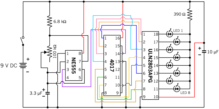 |
Its a bit messy, but if you want to see how the connections appear physically, then this is how they go. I coloured certain wires so theyre easier to follow. |
The speed of the chasing is controlled by the variable resistor on the left. Its good to use 2 L.E.D.s in parallel so they look like theyre following each other. (That would be 16 in total for this particular circuit.) The 3.3 µF capacitor also has an effect on the speed. The capacitor on the right side is just to act as a filter. If youre running it from a 9 V battery, you could probably do without it. If you want to up the voltage, youll need to change the 390 Ω resistor on the right to a higher value. The I.C.s should be happy on 12 V, but I wouldnt crank things too high.
Dual Switch Light Circuit
This was something I saw in hotels in Britain when I was there in 2002. Theyd have a switch by the door, and one by your bed. Either switch could reverse the effect of the other one.
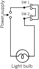 |
This is the basic principle, and it could be used for high voltage, A.C. or D.C. projects. |
As you can see, it just uses 2 SPDT type switches in series with the light. But it could be adapted for other purposes too. It is possible to add a 3rd DPDT switch, which swaps the connections of the right hand side parts of the other switch connections. Maybe you could also add a 3rd switch in some other fashion too, but that was all I could work out. ![]()
Relay Hold Circuit
This simple circuit demonstrates how you can use 2 push buttons to turn a relay on and off.
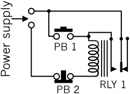 |
Obviously push button 1 is normally open, and push button 2 is normally closed. |
By pressing push button 1, the relay will then turn on, and its own switch will keep it turned on. Pressing push button 2 will turn it off again. This is only to show an example youd probably want a relay with 2 sets of switch contacts to make it practical for turning other stuff off / on. If youre using the relay on a D.C. power supply with semiconductors, like integrated circuits and transistors, its wise to connect a power diode across the relay coil with its anode going to negative and its cathode going to the positive side. (Put it back to front and itll effectively make a short circuit.) This directs any residual current in the coil back into itself.
Polarity Changer Circuit
Using a DPDT switch, you can flip the polarity of a DC power supply.
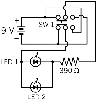 |
This is shown using a slide switch, but it doesnt matter what kind of method it uses. |
With the switch set to the left, only LED 1 will be on. When you move it to the right, only LED 2 will light up. These are only here as an example. You could use such a circuit to test 2 pin bi-colour L.E.D.s, but you may have other reasons for such a circuit too. One other practical purpose would be for DC motors.
Electret Microphone Circuit
I thought making up a circuit for one of my old, unused electret microphones might be a good idea, and then I could have one connected to my main PC, besides my Realistic PZM. Unlike dynamic microphones, electret ones require a power source. I had 2 AAA battery holders which I never used, so that seemed ideal, especially since I also have 8 rechargeable batteries of the same size. I tried an initial circuit with just a resistor and capacitor, in terms of additional components, but found it was a bit quiet. So, out with the transistors for more amplification! I checked some various circuit diagrams to make sure I was on the right track, and in the table below, you can see what I came up with.
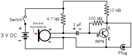 |
In my case, the switch is part of the battery holder, so that saves me using a separate one. The transistor is just a BC547, the capacitors are a regular electrolytic type, and the resistors are all ¼ watt ones. |
The type of plug youll need is just a 3.5 mm mono phono type. (Although some sound cards, and motherboards with built-in circuits may expect a stereo plug, in which case you will need to use a stereo plug and solder the left and right connections together. Thats the plug tip and central ring.) Youll need to connect the negative side of the circuit to the base / bigger part of the plug, and the positive side to the tip. Note that electret microphones tend to be polarised, as they have an internal I.C. of some kind. They may have a red and black wire soldered on, 2 short leads for soldering directly to a PCB, or no wires at all, depending on which one you go for. If you do solder directly to the microphone, you should be very quick about it, as I killed a couple back in the 1990s from overheating.
In terms of mounting, you should put most of the microphone outside of any boxes, as it may reduce the sound quality and cause echoes. I might try and put mine in some foam perhaps. As far as the 4.7 kΩ resistor is concerned, you could probably drop this back to about 2.2 kΩ or so, especially on only 3 V, but this was the closest I had. Speaking of the voltage, using 9 V is probably acceptable as well, and it might be a bit louder too. In this case, substitute the 4.7 kΩ resistor with about 10 kΩ. If this is aimed to be used with your computer, you might be able to run it from the power source of the USB, if you dont mind losing a socket. I was wary about doing so, and thought Id stick with batteries. Plus I dont have any USB plugs anyway. Besides, you could also use this with an amplifier, cassette recorder or whatever else has a microphone socket.
With my Sound Blaster Audigy, I found it great with the 20 dB boost on, but this is just a perceived level. How this relates to real sound levels depends on your amplifier, the volume level, type of speakers, or if youre using headphones. So, you might want to experiment with this yourself. It could vary on your choice of transistor, and voltage level. Even on my bread board I didnt get any interference or distortion, but then I mightve just got lucky. You may wish to use shielded wire aimed for microphones if youre going to place it some distance from the rest of the circuit. Im going to use a prototype board as usual, to hold all the components.
As far as qualitys concerned, it should be good for voice recording, but I wouldnt be 100% sure about recording music. You might want to determine that yourself, if you intend to assemble this anyway.
All in all, this shouldnt cost me any extra, cause I had all the parts already. If youre buying new parts though, the microphones are usually a few dollars at least on eBay. There are some Panasonic ones which are a bit more pricey, but somebody had a bulk pack of 20 generic brand ones for about the same price. ($12.95-ish.)
Id also recommend testing the circuit on a cheaper device first, before connecting it to something like a $4000 PC, and stuffing something up. I just used my Sharp mini hi-fi system.
Lastly, I think most electret microphones have a spherical sound zone, so theyll pick up sounds in all directions around them.
On further testing, I found this to a be a bit distorted on louder sounds. There was clipping at much lower levels than a recorded sound would allow on my computer. In other words, the wave form didnt clip at the top of the display, but rather, at a lower level, which suggests this was a limitation within the microphone circuit, rather than overpowering the input to my sound processor. Im not sure if its to do with the quality of the microphone, or something in the components I used. If you change to 0.1 µF capacitors, it seems to be better, but the frequency range goes up, so bass sounds are less prominent. With 10 µF ones, it seems to have more bass, but there seems to be a recovery period from loud noises. I also thought that maybe the transistor needed to be better. I dont know. I would recommend doing your own tests on a bread board, or a similar set up, to test things before you decide to start soldering up something permanent.
 |
A non-amplified rendition. |
The upper circuit got to be too distorted for me with its amplification implementation, so I decided to revert to the non-amplified circuit shown just above here. The microphone still needs power of course, so the batteries are still present. You could up the voltage to 9 V or so, but you might want a higher value resistor. Maybe 22 kΩ or so. Plugged into my Realtek sound processor, its a little quiet, but pretty clean sounding, since theres no other (external) amplifier noise between the 2. You could use one of course. One thats better than the components I used in the 1st place. ![]() Of course, if you intend this for a regular amplifier, outside of computer use, it should be ideal.
Of course, if you intend this for a regular amplifier, outside of computer use, it should be ideal.
Tips For Mounting L.E.D.s
For folks whove been doing stuff with electronic components all of their lives, this might already be obvious, but if youre new to trying things, do read on!
Apart from using circuit boards to hold L.E.D.s in place, there are a few other methods, when you want to position them in awkward places, or have them separate from the rest of a circuit.  One of my old favourites are polarised header connectors. The technical code for these seems to be KF2510-2P, and if you do a web search for these, youll get exactly what Im on about. The code seems to give more accurate results than any other name for them. You can get these from Jaycar for 90¢ each, including the insert-able contacts. Thats okay for 1 or 2, but if you intend to use a lot of them, you can get packs of 100, including the male pin base part for under $7 from China, if you shop on eBay. They come in fatter versions with more connection points too, which may be useful for RGB L.E.D.s. Theyre actually designed as a pair, so you solder the male part to a PCB, and plug the top part in for some other purpose. Maybe to connect another board, or something. But theyre ideal for L.E.D.s, because the holes have the same spacing. This is useful if you intend to change colours, or just dont want to solder to your diodes. All you need to do then is solder some wires onto the contacts for the plug, slide them into the plastic part until they click in, and youre ready to insert your L.E.D. in the top. They will also hold things in place if you put the diode on one side of a panel, and the socket on the other. But with vibration, they could come loose, so its something you would need to consider.
You can also get specialised L.E.D. holders, usually in plastic, or chrome. The chrome ones give a nice presentation, but they do cost quite a bit more. They used to have great ones of these at Tandy, with a rubber insert at the bottom, and if you find any old ones for sale on eBay from there, these are well worth it for more posh projects. Radio Shack in America might still have these for all I know, but Tandy in Australia is pretty much long gone. (Radio Shack was the company that owned Tandy.) You can also use these together with the sockets above.
A cheapo way to position fibre optic strands against L.E.D.s is to shove a wad of them into an appropriately sized piece of heat-shrink tubing, with the L.E.D. on the other side. I think PMAA type fibre optic cable melts at around 320°C from what I read. So dont use an ultra hot soldering iron. This should be suitable for lighting projects, but probably not for data transfer purposes. You can also buy special connectors for running a single fibre optic strand to a L.E.D.
Make A Lower Power Battery Out Of Yourself
Parts required:
About 16 copper coins, such as old pennies & ½ pennies. Old 2¢ coins may work fine as well.
2 sheets of aluminium foil
A multi-meter
Cut the foil into sizes about 15 cm × 15 cm, or a bit bigger than your hands. Your multi-meter should have a low range, like 2.5 V it doesnt matter if its a digital one with a LCD or an analogue type one with a needle. Place the 2 sheets of foil next to each other, and lay down the copper coins on top of one of them. Attach the positive probe to the foil with the copper coins on top, either with some Blu-Tack or some kind of weight. Attach the negative probe to the other uncovered sheet of foil. Put one hand on this one, and one on the coins. If your hands are a bit sweaty, you may get up to about 0.25 V on your meter. If your coins are a bit tarnished, you can clean them quickly in a solution of salt & vinegar. Wash your hands after trying all this, and do not drink the cleaning solution after the coins have been in it. Maybe if you can get enough coins, and connect about 8 people in series, you might get a L.E.D. to light up.
Make A Custom Battery With Vinegar & Coins
 Parts required:
About 8 copper coins. Pennies from prior to 1966 are best. Other countries look for something else!
A decent sheet of aluminium foil.
A multi-meter.
A L.E.D. which will light up @ around 1.7 V or so.
Thin, plain cardboard. Paper towels may work too. Maybe.
Regular vinegar. The cheap stuff for cleaning is fine.
Some kind of socket with attached wires for the L.E.D., or perhaps alligator clips.
Most batteries are considered to be a dry cell, because they use dry acid. This one will use the vinegar to make a wet cell. Cut up about 10 circles of cardboard & foil at about the same size as the coins. Put the cardboard circles into a small serving jug of vinegar, and then lay down one piece of foil. Leave it sticking out slightly on one side to be a terminal. On top, place a copper coin, next take out a circle of cardboard with some tweezers, and place it on top of the coin. Then add another circle of foil. Repeat this pattern until you have about 8 levels. (Foil, coin, cardboard. Finish with a final coin, but dont break the correct order.) The bottom of the pile is positive & the top is negative. Depending on how clean your copper coins are, the more voltage you will get. (You can clean them in about a minute with vinegar & salt.) Test what you get with the multi-meter, & if it isnt over the maximum voltage rating of your L.E.D. which would usually be around 2 to 3 volts connect your L.E.D. in the correct fashion to the coins and it should light up! If your coins are very clean, and your cardboard is very juicy from the vinegar, you may only need 5 pennies. This is all I have in my picture. Squeezing the coins harder together will increase the amount of juice you get too. If you have time, see if you can get any action with other weak acids, like lemon juice. Oh, and dont use your best coin collection, or valuable pennies either. Some are actually quite expensive! Wash your coins off again with water, when youre done, and then dry them out. If you keep the foil circles, they will corrode after a few weeks and disintegrate into little flakes.
